

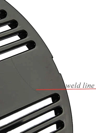
What Are Weld Lines in Injection Molding?
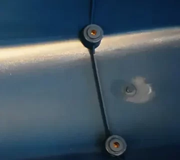
Weld lines, also referred to as knit lines or stitch lines, represent a critical defect in injection-molded plastic components. These linear imperfections occur at the interface where two or more molten plastic flow fronts converge and solidify within the mold cavity. Weld lines are an inherent phenomenon in injection molding, especially prevalent in parts featuring complex geometries, multiple gates, or internal mold obstructions. Understanding their formation mechanisms, impact on part performance, and effective mitigation strategies is paramount for producing high-integrity, aesthetically acceptable molded parts.
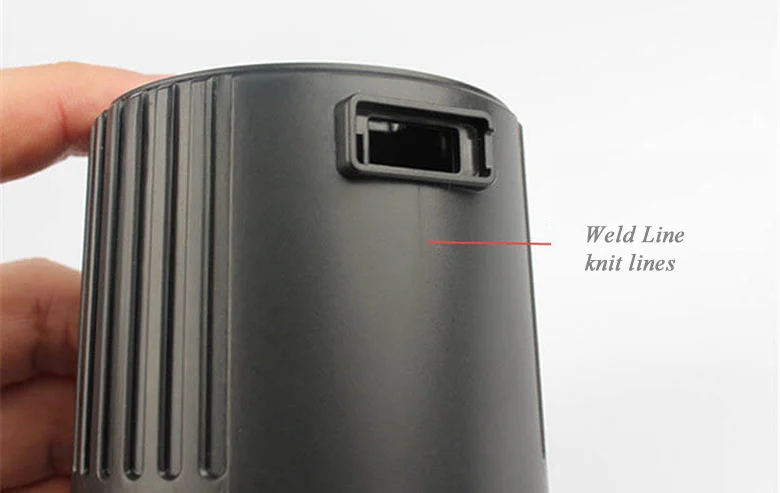
How Weld Lines Form: The Science Behind the Defect
The genesis of weld lines can be attributed to the interruption and subsequent reunion of molten plastic streams during mold filling:
- Flow Front Division
When molten polymer encounters an internal mold feature—such as ribs, cores, inserts, or holes—the primary flow front bifurcates into two or more discrete streams. - Flow Front Convergence
These streams navigate around the obstacle and reconvene downstream, forming a weld line at their meeting plane. - Molecular Bonding Deficiency
Optimal weld line formation requires sufficient thermal energy and pressure to facilitate molecular interdiffusion and entanglement across the flow front interface. Inadequate melt temperature, pressure, or flow velocity at this juncture results in suboptimal polymer fusion. - Rapid Surface Solidification
Accelerated cooling of the polymer’s surface layers impedes the interfacial mixing of the flow fronts, contributing to a visible and mechanically compromised weld line.
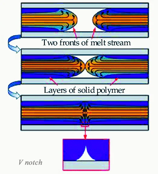
The secret behind weld lines
— Do you know what really causes them?
In injection molding, differences in mold temperature create distinct layers in the molten plastic. The outer layer, touching the mold walls, cools and solidifies quickly, forming a rigid shell. Beneath it, a semi-solid transition layer slows as it solidifies. The hotter core layer in the center stays fluid longer and flows faster than the cooler outer layers. When two flow fronts meet on the part’s surface, this speed difference can cause incomplete bonding, creating a notch-like weld line.
Weld Lines vs Meld Lines in Plastic Injection Moulding
Causes, Differences, and Performance Impact – Learn the Differences Between Weld Lines and Meld Lines
Understand how convergence angles affect molecular bonding, part strength, and overall product quality, with examples and design insights.
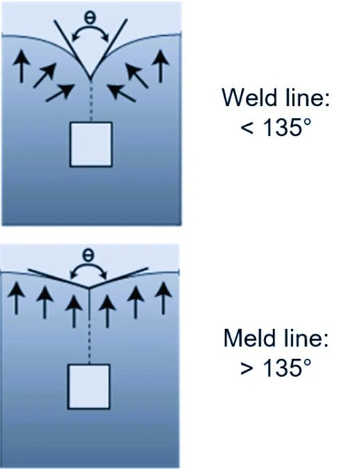
Weld Line
A weld line forms when the convergence angle between two advancing melt fronts is less than 135° (see diagram below). Due to the smaller angle, molecular diffusion at the point of convergence is limited, resulting in a weaker bond in that region. This often leads to reduced mechanical strength. For example, when moulding a plastic component with a hole, weld lines commonly appear where the melt flows around the hole and meets again.
Meld Line
A meld line occurs when the convergence angle exceeds 135°. In this case, the melt continues to flow forward after meeting, allowing greater space for molecular diffusion and entanglement. Compared with weld lines, the molecular orientation in a meld line area is more uniform, and its mechanical properties are significantly superior.
Strategies to Minimize Weld Lines
Weld lines form when molten plastic flows meet and partially fuse. Optimizing mold and part design, processing, and materials helps minimize these defects and improve part quality.
Mold Design
- Optimize Gate Placement: Strategically position injection gates to ensure continuous plastic flow, minimizing the separation of flow fronts and reducing the likelihood of weld lines.
- Reduce Internal Obstacles: Design the mold to avoid unnecessary features such as holes, ribs, or inserts that disrupt flow paths and cause flow front fragmentation.
Part Design
- Uniform Wall Thickness: Design parts with consistent wall thickness to promote even flow and uniform solidification, which helps prevent weld line formation.
- Incorporate Adequate Draft and Radii: Use smooth transitions, appropriate draft angles, and rounded corners to enhance flow cohesion and reduce the visibility and impact of weld lines.
Case Study: Gate Optimization for Figurine Mold
To address uneven filling and enhance product consistency, the original single-point gate was redesigned into a side gate. The new gate was relocated to an area with uniform wall thickness, and its diameter increased from 2 mm to 3.75 mm following the 1.5× wall thickness guideline. Moldflow simulation verified smooth melt flow without material buildup, ensuring stable molding performance.
Result: The optimization improved filling balance, reduced defects, and increased overall production efficiency by approximately 15%.
Process Optimization
- Control Mold Temperature: Maintain mold temperatures that preserve melt fluidity at the weld interface to enhance polymer diffusion.
- Adjust Injection Parameters: Higher injection speed and pressure can improve flow front velocity and fusion.
- Use Mold Release and Surface Treatments: Proper lubrication promotes smooth flow and reduces premature surface solidification.
Material Selection
- Choose Polymers with Favorable Flow Properties: Polymers exhibiting better melt flow and self-welding tendencies reduce weld line visibility and strength deficits.
- Consider Additives: Processing aids or modifiers may improve melt homogeneity and interfacial bonding.
Impact of Weld Lines on Part Quality
Weld lines can negatively impact both the aesthetics and mechanical integrity of injection molded parts:
- Aesthetic Issues: Visible seams or discolorations may diminish the visual quality, which is critical for consumer-facing products.
- Mechanical Weakness: Weld lines often represent zones of reduced tensile, flexural, and impact strength, which can lead to premature part failure under load.
- Stress Concentration: These lines act as stress concentrators, increasing susceptibility to cracking, especially under cyclic or impact stresses.
Primary Causes and Influencing Factors
- Mold Geometry: Internal features such as holes, ribs, and inserts disrupt uniform flow, promoting weld line formation.
- Gate Configuration: Multiple gates or poorly positioned single gates can create separated flow fronts prone to welding defects.
- Material Characteristics: Polymers like ABS and other amorphous resins are inherently more susceptible due to their flow behavior and melt rheology.
- Processing Parameters: Suboptimal melt temperature, injection speed, and mold temperature exacerbate weld line severity.
Design for Manufacture (DFM)
Effective mold maker collaboration drives quality and efficiency.
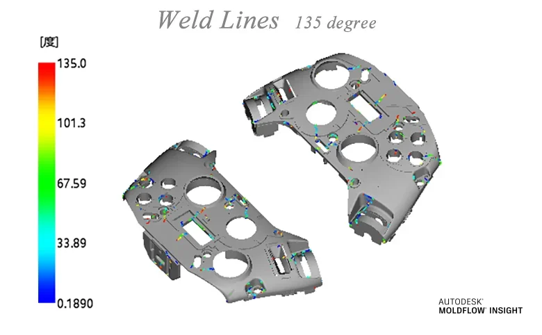
Identifying potential weld line locations early in the DFM phase enables proactive adjustments to part and mold design. Close collaboration with mold makers during quoting and tooling design is essential to address cosmetic and structural concerns related to weld lines. Such early-stage communication ensures balanced decisions between mold complexity, cost, and part quality, ultimately leading to better manufacturing outcomes.
Best Practices for High-Quality
Weld lines are an unavoidable challenge in injection molding due to the nature of polymer flow within complex mold geometries. However, through a detailed understanding of their formation mechanisms, impacts and a combination of strategic design, processing, and material decisions, manufacturers can effectively minimize their occurrence and severity. This comprehensive approach ensures that molded parts meet both aesthetic and functional requirements, thereby maximizing product performance and customer satisfaction.