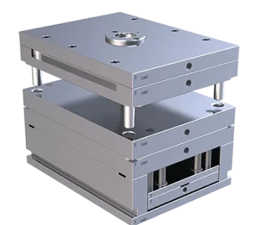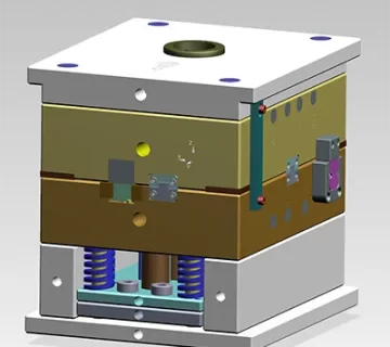


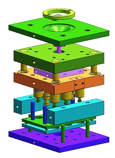
When developing molds for mass production, designers often treat plastic injection molds and die-casting molds as similar mould tools. However, despite sharing common elements—core, cavity, gating, cooling, and ejection—the two mold types operate under fundamentally different principles.
Understanding these differences is crucial for achieving reliable part quality, extending mold life, and reducing overall manufacturing cost.


Injection Mold vs. Die Casting Mold
- Injection molding: molten polymers, sensitive to wall thickness and shrinkage.
- Die casting: molten metal (Al, Zn, Mg), higher temperatures and pressures, less shrinkage sensitivity.
Key takeaway: design allowances for shrinkage, draft, and wall thickness differ significantly between the two processes.
Runner & Gate Design
| Item | Injection Mould | Die Casting Mould |
|---|---|---|
| Runner size | Balanced, minimal material waste | Must be large to reduce pressure loss |
| Gate thickness | Typically thin | Thin but wide (0.3–0.8 mm) |
| Material reuse | Regrind limited | Overflow runner 100% recyclable |
For die casting, runners and overflow wells help stabilise metal flow and trap impurities, improving surface quality and dimensional consistency.
Venting System (Air Release)
Because molten metal fills the cavity very quickly and under extreme pressure, proper venting ensures trapped gas escapes.
| Injection Mould | Die Casting Mould |
|---|---|
| Standard micro vents | Venting + overflow wells (slag traps) |
| Lower risk of gas entrapment | Vent thickness transitions from thick to thin |
A well-designed venting system directly affects part quality and eliminates gas porosity.
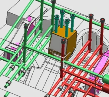
Cooling System (Water Channel Layout)
Cooling design plays a central role in cycle time and mould life.
| Injection Mould | Die Casting Mould |
|---|---|
| Cooling channels designed for stable shrinkage control | Cooling channels designed for thermal shock protection |
| Standard O-rings | Must use heat-resistant O-rings |
| Nozzles may be embedded | Nozzles remain exposed for easier maintenance |
Since die-casting moulds see high thermal shock, water circuits are designed for fast temperature dissipation and safety.
Mould Steel and Structural Strength
| Factor | Injection Mould | Die Casting Mould |
|---|---|---|
| Recommended steel | P20 / 718 / S136 | H13 / 8407 / 2344 ESR (heat-treated) |
| Core & cavity thickness | Standard thickness | 20 mm thicker than injection moulds |
| Heat treatment | Optional | Mandatory |
Die-casting moulds must withstand extreme temperature and pressure, requiring heat-treated, high-strength steels.
Die-casting moulds usually adopt a simpler two-plate structure but require hard machining and mandatory heat treatment.
Alignment and Positioning
Alignment and Positioning
Die-cast parts are prone to flashing due to molten metal pressure. Therefore:
Die casting does not use zero-degree positioning
Instead, it uses tapered or angled alignment for increased rigidity
This reduces mould damage and ensures stable fitment during repeated cycles.
Ejection System
Because metal contracts when cooled, ejection design must be precise.
| Injection Mould | Die Casting Mould |
|---|---|
| Standard ejector pin layout | Must match the machine’s ejector rod layout |
| Smooth ejection required | Strong mechanical ejector system |
| Lower load and stress | Higher force required due to metal shrinkage |
Any mismatch leads to uneven ejecting force and mould damage.