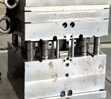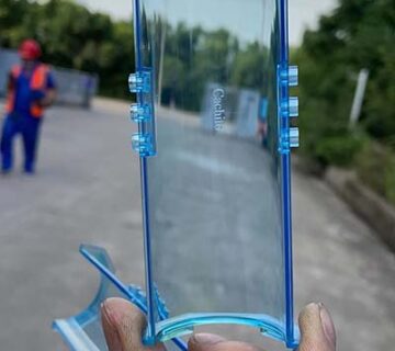


In injection molding, the runner system serves as a critical channel linking the injection machine’s nozzle to the mold cavity. Its primary role is to guide molten plastic smoothly and uniformly into the cavity to ensure complete and consistent filling.
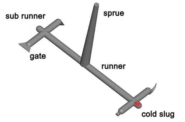
A typical runner system consists of the sprue (main runner), branch runners (sub-runners), gates, and cold slug wells. Selecting the appropriate runner design requires a comprehensive evaluation of product geometry, material properties, and production demands.
1. Types of Runner Systems and Their Applications
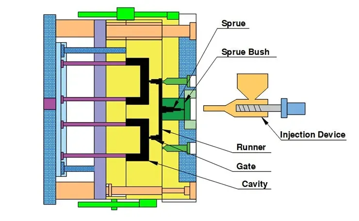
▪ Sprue (Main Runner)
The sprue is the initial passage through which molten plastic enters the mold from the injection nozzle. Typically conical in shape, it facilitates easier ejection of the solidified material (cold slug).
Key Characteristics:
- Tapered design (1°–3°) for efficient demolding
- Inlet diameter is 0.5–1 mm larger than the nozzle to ensure proper fit
- Connects downstream to branch runners or directly to the gate
Applications:
Required in all molds. In single-cavity molds, it may connect directly to the gate, whereas in multi-cavity molds, it feeds into branch runners.
▪ Branch Runners (Sub-Runners)
These channels distribute molten plastic from the sprue to multiple cavities or various regions within a single cavity.
Common Cross-Sections:
- Round: Offers minimal flow resistance but is costly and complex to machine; ideal for long flow paths or high-flow materials
- Trapezoidal: Balances efficiency and ease of machining; most widely used (recommended height-to-width ratio ~3:4)
- U-Shaped / Semi-Circular: Simpler machining, moderate flow efficiency; suited for general applications
- Rectangular: High flow resistance; typically used for thin-wall components or special designs
▪ Gate
The gate connects the runner system to the cavity. As the narrowest section, it controls flow rate, pressure, and filling timing, while enabling automatic detachment of solidified material during mold opening.
Design Considerations: Gate design directly influences part quality and filling behavior and must be chosen based on material type, part geometry, and surface finish requirements.
▪ Cold Slug Well
Located at the end of the sprue or sub-runner, this recessed feature captures cooled material that initially contacts the mold surface—preventing defects such as short shots or cold flow marks.
Typical Shapes:
- Conical or spherical
Function:
- Enhances part quality by preventing premature cooling material from entering the cavity
- Often used with pull pins to extract the cold slug during ejection
2. Classification by Temperature Control
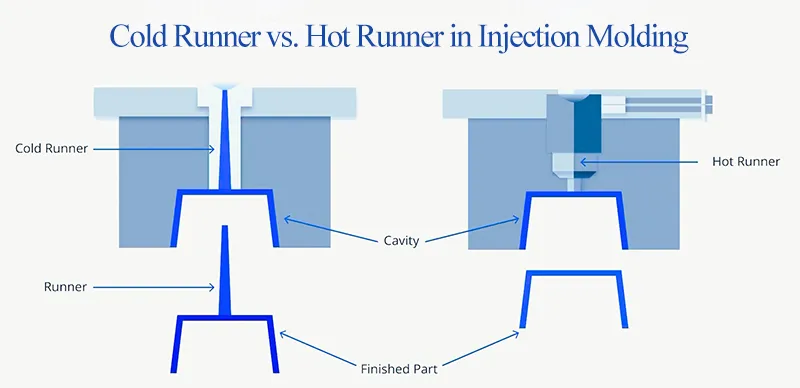
Cold Runner System
Cold runner systems use unheated channels to convey molten plastic from the injection unit to the mold cavities. After each molding cycle, the runner solidifies along with the part.
Structure:
Constructed from standard mold steels (e.g., P20, 718H), cooled via the mold’s integrated cooling system.
Advantages:
- Simple mold design with 30–60% lower tooling cost than hot runners
- Compatible with all thermoplastics, especially heat-sensitive materials like PVC
- Easy maintenance with no heating components required
Disadvantages:
- Material waste: 10–30% of plastic is lost as solidified runners
- Requires manual or automated runner separation post-molding
- Increased injection pressure due to cooling in the runner system
Best Suited For:
- Low-volume production
- Frequent material or color changes
- Cost-sensitive projects
- Molding of heat-sensitive polymers
Hot Runner System
Hot runner systems use electrically heated components to maintain plastic in a molten state throughout the runner system. Only the finished part is ejected, eliminating runner waste.
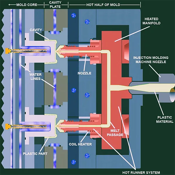
Key Components:
- Hot Runner Manifold: Maintains melt temperature while distributing plastic to each cavity
- Heated Nozzles: Deliver molten plastic directly to the gates
- Temperature Control System: Ensures ±1°C precision across the system
Hot Runner Types:
- Open Nozzle: Economical and simple; may cause stringing or drooling—less ideal for low-viscosity materials
- Valve Gate Nozzle: Integrated valve pin provides precise shut-off, suitable for precision parts and low-viscosity materials like PE and PP
Advantages:
- Over 95% material utilization with zero runner waste
- Stable melt temperature with reduced pressure loss
- Improved aesthetics and minimized weld lines
- Enables full automation with no runner separation needed
Disadvantages:
- 50–200% higher tooling costs than cold runners
- Requires advanced thermal control and maintenance
- Not recommended for heat-sensitive or abrasive materials (e.g., glass-filled compounds)
Best Suited For:
- High-volume production
- Aesthetic-critical or dimensionally demanding parts
- Thin-wall precision components (e.g., electronics housings, connectors)
3. Special Runner Designs
▪ Submarine Runner (with Tunnel Gate)
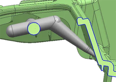
The submarine runner, also known as a tunnel gate, is concealed beneath the mold’s parting line or integrated with ejector pins. It automatically detaches during the part ejection process, eliminating the need for manual trimming and improving appearance.
Best For:
- Aesthetic-critical components with minimal visible gate marks
- Consumer electronics housings
- Automotive interior parts
▪ Fan Runner
The fan runner features a progressively widening geometry that ensures uniform melt flow across wide surfaces. This design helps minimize weld lines and material stress, reducing the risk of warping in thin-walled parts.
Best For:
- Large-area, thin-wall plastic parts
- Automotive dashboards
- Instrument panels and film components
| Gate Type | Advantages | Disadvantages | Primary Applications |
|---|---|---|---|
| Submarine Gate (Tunnel Gate) |
|
|
Large, thick-walled industrial components (e.g., containers, crates, thick panels) |
| Direct Gate (Center Gate) |
|
|
Small to medium general-purpose parts such as toys, housings, and tools |
| Edge Gate (Side Gate) |
|
|
Medium-volume production with moderate appearance requirements |
| Pinpoint Gate (Needle Gate) |
|
|
Precision small parts in electronics and cosmetics |
| Hidden (Submarine) Gate |
|
|
High-appearance parts with curved or irregular geometries (e.g., consumer electronics, automotive interiors) |
| Fan Gate |
|
|
Large thin-walled parts like dashboards and instrument panels |
| Ring Gate |
|
|
High-precision circular components such as lenses and bottle caps |
Runner System Selection Guidelines
Choosing the optimal runner system is essential for achieving efficiency, product quality, and cost-effectiveness in injection molding. The table below outlines recommended systems based on key production priorities:
| Priority | Recommended System |
|---|---|
| Cost-sensitive production | Cold runner system |
| Material savings / Automation | Hot runner system |
| Multi-cavity consistency | Balanced runner layout |
| High aesthetics / Automation | Submarine runner or hot runner system |
Note: Final selection should be based on product geometry (size, wall thickness), material characteristics (flowability, thermal sensitivity), and production volume. Where applicable, mold flow analysis should be performed to ensure balanced pressure distribution and efficient flow paths.
Expert Support from DSW
At DSW, we offer custom injection molding solutions, including insert molding, overmolding, and standard plastic injection molding. Our engineering team can assist you from design validation and mold flow analysis to prototyping and production.