

Introduction
The mold gating system is one of the most critical elements in plastic mold design. It determines how molten material flows into the cavity and directly affects product appearance, dimensional stability, and structural strength.
A well-designed gating system ensures smooth flow, balanced filling, and efficient cycle time. The following principles summarize the key considerations in gating system design.
Design Principles
(1) Geometrical Balance in Multi-Cavity Molds
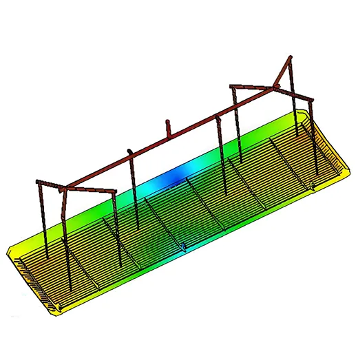
For multi-cavity molds, use a geometrically balanced runner layout to ensure all cavities are filled simultaneously.
Figure 1-1: Example of a balanced runner layout.
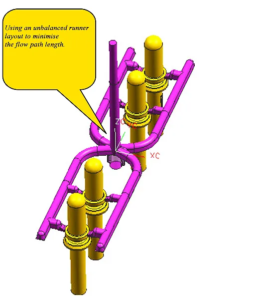
If a non-balanced or multi-gate layout is required, adjust the gate widths or runner sizes according to mold-flow analysis results to achieve uniform filling.
Figures 1-2 & 1-3: Non-balanced layout and flow adjustment example.
(7) Easy Gate Removal
Gates should allow easy or automatic removal without damaging the product surface or affecting aesthetics.
(2) Short and Straight Runner Design
Runners should be as short and straight as possible to reduce heat and pressure losses. All corners must include smooth radii (R) to maintain continuous flow.
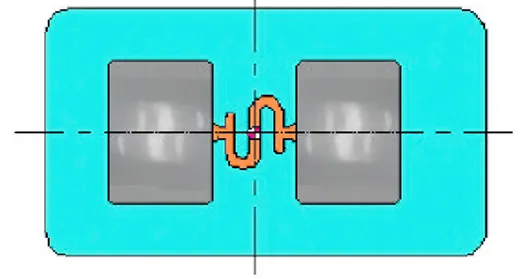
For transparent materials such as PC and PMMA, use an S-shaped runner to prevent cold slugs from entering the cavity and creating flow marks.
Figure 1-4: S-shaped runner for transparent parts.
(3) Runner Surface Finish
| Application | Recommended Polishing Grit |
| Standard parts | #320 or finer |
| Mirror-finish parts | #600 |
A smoother surface reduces flow resistance and minimizes material degradation.
(4) Cold Slug Well Design
Each runner end must have a cold slug well to capture solidified material and prevent it from entering the cavity.
In small gate designs, the gate must not face directly toward the main runner.
Figure 1-5: Example of proper cold slug well and gate orientation.
(5) Complete and Controlled Filling
The gating system must guide molten resin to fill every corner of the cavity while allowing trapped air to vent smoothly through properly designed vents.
(6) Prevention of Molding Defects
Proper gating design helps avoid:
- Short shots
- Sink marks or shrinkage
- Warpage or deformation
- Flash
- Dimensional deviation
Figure 1-6: Examples of molding defects caused by poor gating design.
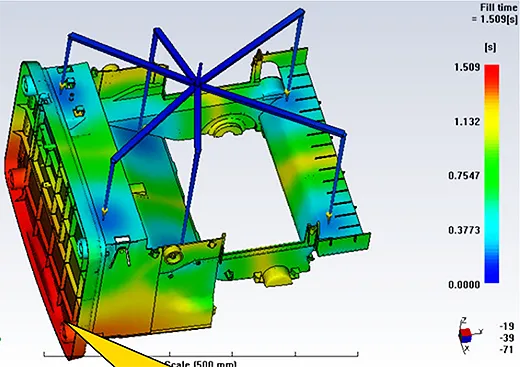
Figure 1-6B: High-quality plastic part after adjusting runner size and gate location.
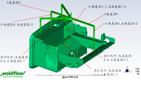
(8) Automation Compatibility
Runners should be designed for robotic extraction to enhance automation and reduce manual labor.
(9) Runner Cross-Section Design
- Round runners (best flow performance)
- U-shaped runners (easy machining and cleaning)
These profiles reduce pressure loss and simplify processing.
(10) Runner Weight Control
Control runner weight during design to keep production efficient:
- Runner weight should not exceed quoted material usage.
- The runner-to-total shot weight ratio should be ≤ 25%, and ≤ 50% in exceptional cases.
If the limit is exceeded, a written notice must be submitted to the project engineer.
(11) Multi-Gate, Single-Cavity Molds
The number and size of gates depend on the flow length-to-thickness ratio (L/T) and mold-flow analysis. Proper design helps minimize weld lines that may weaken the part or affect its appearance.
Table 1: Typical Flow Length Ratios for Common Plastics
| Material | Flow Length Ratio (L/T) | Remarks |
|---|---|---|
| ABS | 150:1 | Good general-purpose resin |
| PC | 100:1 | High viscosity |
| PMMA | 120:1 | Transparent, needs S-runner |
| PP | 200:1 | Long flow capability |
| PA66 | 180:1 | Excellent fluidity |
(12) Multi-Cavity Molds with Different Parts
When a mold produces different parts, use mold-flow analysis to define gate and runner dimensions to ensure all cavities fill simultaneously.
Figure 1-7: Mold-flow balance for multi-part cavities.
(13) Interchangeable Gate Inserts and Flow Adjustment
Use interchangeable gate inserts to selectively enable or disable cavities as needed.
To maintain balance during molding, flow adjustment valves can be added to restrict flow on the easier-filling side.
Figures 1-8 (a) & (b): Example of interchangeable gate insert and adjustable runner valve.
(14) Symmetrical and Compact Layout
Multi-cavity layouts should be symmetrical, compact, and balanced to:
- Prevent uneven clamping force
- Reduce runner weight
- Decrease mold size and machine tonnage
Figure 1-9: Comparison of rational and irrational layouts. Improper designs can cause flash, dimensional error, and imbalance. Evaluate all layout options for the most efficient configuration.
(15) Eccentric Mold Design Considerations
- Offset should be toward the vertical (top-bottom) direction.
- The offset S must be less than 10% of mold length (L).
- Ejector pins should follow the offset, using two or more pins to maintain balanced ejection.
Figure 1-10: Eccentric mold structure and ejector positioning.
3. Conclusion
A well-engineered gating system forms the foundation of a successful mold design.
By following these principles, designers can achieve:
- Consistent filling and balanced cavity pressure
- Reduced molding defects
- Easier automation and maintenance
- Lower material waste and production cost
A scientific approach to gating system design not only enhances product precision and appearance but also significantly improves manufacturing efficiency and reliability.