


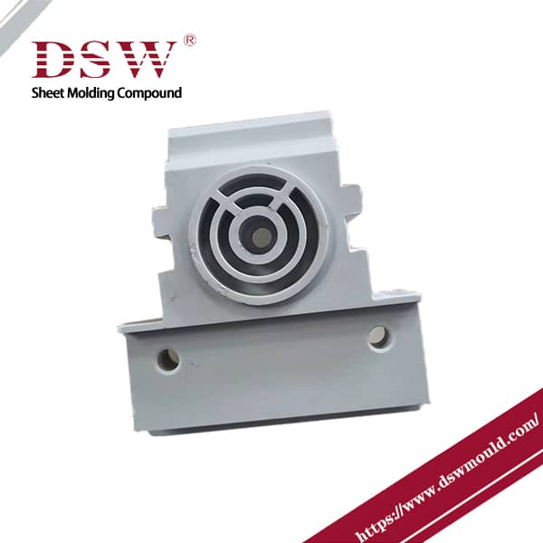
What causes ejector marks on injection-molded parts?
Ejector pin marks are glossy or white imprints on the surface of an injection molded product, typically found opposite the location of the ejector pin. The factors causing ejector pin marks can be categorized as follows:
Product design:
-
- Inappropriate product thickness: Excessively thin walls hinder cavity filling and can lead to ejector pin marks.
Mold design:
-
- Inappropriate gating system design: Narrow runners, long main runners, and sharp turns increase flow resistance and affect plastic filling.
- Inappropriate gate design: Small gates cause high flow resistance and orientation stress, leading to marked areas with high stress.
- Inappropriate ejector mechanism design: Improper size, location, and quantity of ejector pins on plastic parts.
- Inappropriate mold cooling channel design: Uneven cooling of the product within the cavity.
- Inappropriate mold venting system design: Insufficient venting causing vacuum conditions in the cavity.
Machine parameters:
-
- Inappropriate injection parameters: Improper control of injection pressure, speed, and switching position.
- Inappropriate holding pressure parameters: Incorrect control of holding pressure, speed, switching position, and backpressure level.
- Inappropriate mold temperature parameters: Improper temperature settings for mold core, cavity, and cooling channels.
- Inappropriate material temperature parameters: Incorrect temperature settings for different sections of the barrel.
- Inappropriate ejection parameters: Improper ejection speed, pressure, and type.
- Inappropriate clamping force parameters: Improper machine tonnage selection and clamping force settings.
How to Eliminate Ejector Pin Marks in Injection Molding
To address the causes of ejector pin marks, the following solutions can be implemented:
Product design:
-
- Ensure appropriate wall thickness based on material and product structure, generally not less than 2.5mm for simple structures and 2.8mm for complex structures with ribs.
Mold design:
-
- Adjust the sizes of the sprue and runner to alleviate injection pressure overshooting caused by filling difficulty.
- Properly locate the gate to facilitate cavity filling and minimize stress concentration.
- Design ejector pins on ribs to distribute ejection force evenly.
- Consider ejecting at stress points on deep ribs to avoid excessive force causing ejector marks.
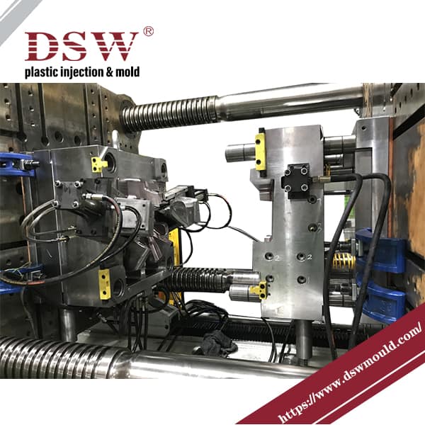
Injection Machine parameters:
-
- Select an appropriate injection molding machine.
- Control process conditions, including mold temperature, processing temperature, injection speed, pressure, holding pressure, time, and cooling time.
- Optimize processing temperature, injection pressure, speed, and time.
- Adjust holding pressure and time when the product is more than 90% injected.
- Ensure sufficient cooling time before ejection to prevent defects.
By considering these factors and implementing the appropriate solutions, the occurrence of ejector pin marks can be minimized in the injection molding process.


No comment